Friday, November 16, 2012

Project Video

Title: From nothing to something
Objectives:To show the outcome (manufacture) of this final year project
                    To show the overall process of this project
 
Content: The first figure is to show you the transformation of the project which is from basic exercise bike to exercise bike generator.
The second approach is the video of this project. It includes two option in charging the battery. The first one being introduce is the manual method and the second one is the automatic method.

Before and after of Alternator Pedal Generator


INDUSTRY DAY!-FYP PRESENTATION

Week 14

The day had come!Alhamdulillah I managed to finish my final year project at the desired time. I would like to thank to my fyp supervisor, Miss Pusparini as she is helping me so much in developing this project. Not forgotten to my friends that always support me throughout the period until I managed to complete my project.  Here, I attach my fyp poster...During the presentation, I used to explained based on the poster that I provide. For my poster, the content includes:
  • Introduction
  • Objectives
  • Application
  • Methodology
  • Result
  • Advantages
  • Conclusion 
  • Reference
     

Project Flow

Title: Project Methodology
Objectives: To figure out the flow of the project

After thinking for a period of time, I decided to further developed my project method. There will be two methods in charging the energy either by apply it manually or automatically. Below is the picture of my project flow...

Wednesday, November 14, 2012

Last but not least

Title: Motor and alternator coupling
Objective: To make sure that the motor can rotates the alternator
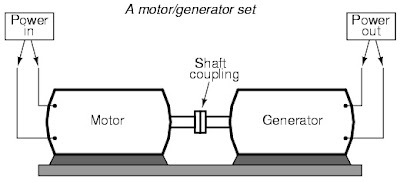
Content: The last method I will have is by having the AC motor. Meaning that in order to rotate the alternator automatically the motor is needed. What the reason that I wanted to make it automated? As to know that this project having a mat. So whenever people touch the mat the system will work automatically. Alright to make it happen, I will couple the shaft of the alternator and motor. As they are coupling therefore at the time of the motor is rotate the alternator will rotate as well. 
Furthermore, I will used the AC motor instead of using DC motor. Why? As can see that to move the alternator is quiet hard so it needs higher input power. The motor that suit could be a DC motor but for this time I just found the AC motor-washing machine AC motor. Therefore the coupling will be like this...

Analysis: After the coupling have been done, I found that the alternator moves very smooth. I can conclude that the motor I used is just suit with the alternator.

The way they were coupling

Wednesday, November 7, 2012

Result!

WEEK 13

Title: Result obtained when charging system takes place
Objective: To make sure the result that will be getting is about 13.5-14.4V.

Content: After belting system have been made in this project, the result is then being observed to determine the right output voltage. As the multimeter is connected to the battery, the reading is then recorded. The result obtained is 14V. Just nice with the theoretical data where in order to charge battery, the output voltage that will getting must be more than 12V and between 13-14V.
''
Charging System Basics
The electrical system in an automobile is said to be a 12 volt system, but this is somewhat misleading. The charging system in most cars will generally produce a voltage between 13.5 and 14.4 volts while the engine is running. It has to generate more voltage than the battery's rated voltage to overcome the internal resistance of the battery. This may seem strange, but the current needed to recharge the battery would not flow at all if the charging system's output voltage was the same as the battery voltage. A greater difference of potential (voltage) between the battery's voltage and the alternator's output voltage will provide a faster charging rate.
As long as the engine is running, all of the power for the accessories is delivered by the alternator. The battery is actually a load on the charging system. The only time that the battery would supply power with the engine running is when the current capacity of the alternator is exceeded or when engine is at a very low idle.                                                       
                                                                                                                                                                      ''

Analysis: The alternator diagram must be just like below...otherwise the output voltage can't be observe...Where can see that a fuse is connected in series with the battery as to ensure that to the battery will not drained or damaged.
Circuit diagram of the alternator

Thursday, November 1, 2012

Up-to-date FYP Project

Title: Latest progress
Objective: To identify the current problem
                    To solve the problem.
Content: For my project, I decided to change my project method a little. This time around, there will be no spring at all. Through all the difficulties outcome, I found out that the alternator is not going to move smoothly without a belting system. And of course to prevent that problem to occur again then I used to upgrade my project with a drive belt. After doing that, I also found out that in order to have high output voltage from the alternator the input power or human power should be more powerful, if not it will be zero voltage.
Here I attach my latest progress of fyp....


Wednesday, October 24, 2012

Belting is necessary....

WEEK 12

Title:Belting system
Objective:To improve the efficiency of this project

Content: Since my project just have the alternator straight away attached to the flywheel therefore I wanted to do some improvement in terms of its efficiency. Without a timing belt my project will not going to work as the belting system helping so much to run the alternator smoothly. First of all, I will to make sure the alternator's pulley is fit enough with the flywheel. Only then the belt can be paired.

Analysis: By doing some observation, I decided to change the pulley of the alternator. The original size of the pulley is very small to place the belt therefore I have change into a bigger one. After the changes have been done, the belt is then paired between the alternator and the flywheel. The problem is solved. 

Belt no series/type:4pk1705

Thursday, October 18, 2012

Why using alternator rather than generator?

WEEK 11

Title: The purpose of using alternator
Objectives: To clarify the importance of the alternator for this project.
                   To differentiate the alternator and the generator operation
 
Alternators
Alternators can produce much higher output than generators; current designs on produce over 160 amps. The brushes only carry current to power the rotor (about 7 amps, maximum), so they last far longer than generator brushes do. There are some disadvantages, though. The Lundell alternator requires two watts of power to spin for every one watt that it produces, making it relatively inefficient.

Generators
One of the advantages of generators was very clean electrical output, since they produced pure DC. However, all the current had to travel through the brushes and brush leads; this produced a lot of heat, and when the brushes would pass over the bars in the commutator, small electrical arcs would be produced, which shortened the life of the brush. To counter this, the brushes were made very hard, which wore out the commutator faster. Because all current traveled through the brushes, most generators had a maximum output of 50 amps.

Generators also needed a cut-out relay to disengage power to the generator when not charging. This was done so that the generator would not pick up power and turn into a motor, burning out when not being spun by the engine.

Tuesday, October 9, 2012

connection

WEEK 10

Title: The assembly of the alternator to the flywheel
Objective: To show how the alternator is rotated at the time the flywheel is also rotates.


PLANNING...

WEEK 10

Title:How to make the bike as a mat?
Objective: To determine the way this project being presented in a clear image

Content: In order to make the bike as a mat, the main thing to modify is the pedal. Imagine that the exercise bike is in the wall, and let the pedal be out of the wall. Therefore there will be only the pedal being seen by people from outside. Alright now focus to design of the pedal, to make it efficient to be used by people, the pedal must be wider that the original pedal. Therefore, the width of the pedal must be adjusted into certain width which can be pressed even people is quite a distance from the wall. At the end of it, the pedal will be look as a mat. Just by wrapping it with cloth based material or anything.

One thing to be considered is how easy people reach the pedal? The easy way is to make some stage. Meaning that there will be a stage being placed near the pedal. In reality the stage will be a platform for people to step in.

Clear image of the project

Monday, October 1, 2012

Springs and its role

WEEK 9

 Title: Springs functionality
Objective: To describe the springs' role and to determine its operation
Content:The procedure to connect the spring with the bike together with its function when the pedal is pressed.

For this week I focusing on the design of the power pedal. But before that, the exercise bike must be modified into something that I want in to be. Therefore, the first thing is I want to connect the spring to one of the exercise pedal. How I want to connect the spring to the pedal? First of all, I will remove the pedal's base as you can see at the picture of the left side the one which is black in color. By removing the base, only then I can make the pedal holder to hold my spring. Alright let see the picture below....
Modification of one side of the pedal
From the picture when the base is removed the thing left is the pedal holder. Now, I will place a hook onto the pedal holder. The hook will hold the springs. But in order to make sure the spring is strained enough therefore I will fasten a rope to it from one end of the exercise bike. The spring will be like below....

 
How the bike is operate when the springs is being connected? The video shows that when the spring is presence, it forces the flywheel to keep rotate but in different direction. The rotation with presence of the springs is much higher than without the springs.  

Analysis: The advantage is that by pressing the pedal once the flywheel will rotates as much possible according to as much as the given pressure while pressing the pedal. As a result, the springs helping the flywheel to rotate more and the time period of the flywheel to stop rotate will be long. 


Saturday, September 29, 2012

Charge controller- Is it necessary?

WEEK 8

Title: charge controller
Objective: To know how much this project need the charge controller.
Content: Remember the previous post where I have given a link that contribute to develop this magic mat? As I go through the web page I saw some interesting component that may used for this project. The component that I want to discuss is the charge controller. Look at below description regarding the component. 

Q: WHY SHOULD YOU USE A CHARGE CONTROLLER TO CHARGE YOUR LEAD ACID POWERPACK BATTERY WITH SOLAR / WIND / PEDAL POWER?    

Short & Easy Answer: Because if you pedal too fast and generate too high of a voltage from your bike generator, you could dramatically shorten the life of your battery / powerpack.basic pedal power charge controller configuration

Longer more technical answer:  Your battery / power pack has a limit on how high of a voltage it can see while charging.  One term to describe this voltage is called the "Peak Charge Voltage".  If you pedal too fast and generate too high of a voltage, then you could exceed the peak charge voltage and supply your battery with too much current.  This would damage the cells inside and affect their ability to take a charge. 
 In most cases the peak charge voltage for a lead acid / AGM (absorbed glass mat) battery / powerpack is somewhere near 14.8V DC (V= Volts DC= Direct Current).

Analysis: But here, I wondering that the charge controller really can be used for this project. Is it necessary or not? I hope right after this project is work out then this question will be answered, depending on the value of the output comes out.

Reference:  http://pedalpowergenerator.com/PPG-12-200-nc25a-charge-controller.htm

Monday, September 24, 2012

Mechanical Part

WEEK 8

Title: Pedal and Generator
Objective: To determine the basic operation of the project.
Content: Let be clear. This project is more toward the mechanical part. As it consumes more on power pedal, therefore I must concentrate on the pedal itself. Pedal power is the transfer of energy from a human source through the use of a foot pedal and crank system. As we can see, the image that I provide is about two different thing. But this two different thing is totally related to each other. The one is the pedal system and the other one is generator or alternator.  The basic operation of this project is when sufficient amount of power is applied by means of pedal's pressing through pulley and belt, then it provide a continuous reaction toward the shaft of alternator. At the same time, the flywheel continue to rotate in presence of the spring. Thus, the system will not require much input power, but only a few touch to it. 

Analysis: The image shows that 1 turn in pedal power provide 4 turns in generator/alternator. It gives a greater output at the end.
Pedal Generator
Operation of power pedal

Monday, September 17, 2012

PICTURES

Title: Progress...
Objectives: To select the suitable component to do this project

Content: This project require a basic things as mentioned previously in my post. Without those things this project will not be conducted smoothly. Alright below is the image of the spring I found at the same place of the baby cradle is sold. I also bought the hook so that I can place the spring onto it. Besides, i also bought the car alternator where I found it at the car workshop. Meanwhile the pulley and belt are hard to find. Seems i have to buy it at the internet. Therefore, I had found one in mudah.com which is suitable to be fitted in this project. Whereby it come out with the flywheel and pedal. 

exercise bike
car alternator
spring

Thursday, September 13, 2012

PROCESS

WEEK 7

Title: Description of the whole process
Objective: To clarify the whole process in making this project
Content:Below is the clear image of this project. Where i found it more efficient in making more output power. This is because i use the alternator instead of the build in magnets and solenoids.

Sketching of the overall project

As can see here, there have a pedal, pulley and belt, alternator, spring and last but not least a battery. The pedal act as an input mechanism. There have two inputs which is from the left and the right. People may step at both directions in order to get the output power. Below the pedal, we can see is the spring, which is it's helping the pedal to go back into its position. While the pulley and belt is function as the catalyst of energy reaction brought by the pedal toward the shaft of the alternator . Alternator will then rotates which gives a power to it. This power will convert into electrical power.

Analysis:
Based on the process above, it showed that the alternator will convert the mechanical energy to electrical energy in the form of alternating current. Let's refresh about the principle operation of the alternator..

" Alternators generate electricity using the same principle as DC generators, namely, when the magnetic field around a conductor changes, a current is induced in the conductor. Typically, a rotating magnet, called the rotor turns within a stationary set of conductors wound in coils on an iron core, called the stator. The field cuts across the conductors, generating an induced EMF (electromotive force), as the mechanical input causes the rotor to turn."                                http://en.wikipedia.org/wiki/Alternator

Wednesday, September 12, 2012

UPDATE

WEEK 7

hello readers!
 Alright for now i just update a link. Just to show you that this link is helping me so much..!The link provide me a basic idea and also provide the way to do it....There is about 5 steps in making the thing. I enjoy the learning process very much!

http://pedalpowergenerator.com/free-diy-bicycle-generator-video-gallery_3_nc25a-charge-controller.htm

Saturday, September 8, 2012

Announcement

WEEK 6

Title: Change in method in making the magic mat. No more solenoids.
Objective: To solve the problem by making it in another way

Content: Since I'm still can't thinking another way to do the mat...I decided to change my method in constructing the mat...The method that i used to have will be different from previous-which is different in terms of its (method). I am still using the electromagnetic induction but for this time the principle came from the alternator itself. 
Remember that my last time proposal, I used to have a project that can contribute benefit to the consumers. The project should not being noticed by people surrounding. Therefore, I am still make it that way. For this time, the method is easier than previous. And I hope that my present project will success. I hope so....

Here we are!

Based on the figure above, energy system can be divided into three types which is energy in, energy store and energy use. The energy that I wanted to have in my project is pedal power categorized as an energy in...The pedal power is actually the source of energy. Same goes to magic mat, whereby the magic mat is used pressure comes from people's steps. Later i will show you the sketching and the things I bought for this project. Power pedal construction is still in progress.....