Friday, November 16, 2012

Project Video

Title: From nothing to something
Objectives:To show the outcome (manufacture) of this final year project
                    To show the overall process of this project
 
Content: The first figure is to show you the transformation of the project which is from basic exercise bike to exercise bike generator.
The second approach is the video of this project. It includes two option in charging the battery. The first one being introduce is the manual method and the second one is the automatic method.

Before and after of Alternator Pedal Generator


INDUSTRY DAY!-FYP PRESENTATION

Week 14

The day had come!Alhamdulillah I managed to finish my final year project at the desired time. I would like to thank to my fyp supervisor, Miss Pusparini as she is helping me so much in developing this project. Not forgotten to my friends that always support me throughout the period until I managed to complete my project.  Here, I attach my fyp poster...During the presentation, I used to explained based on the poster that I provide. For my poster, the content includes:
  • Introduction
  • Objectives
  • Application
  • Methodology
  • Result
  • Advantages
  • Conclusion 
  • Reference
     

Project Flow

Title: Project Methodology
Objectives: To figure out the flow of the project

After thinking for a period of time, I decided to further developed my project method. There will be two methods in charging the energy either by apply it manually or automatically. Below is the picture of my project flow...

Wednesday, November 14, 2012

Last but not least

Title: Motor and alternator coupling
Objective: To make sure that the motor can rotates the alternator
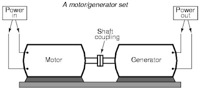
Content: The last method I will have is by having the AC motor. Meaning that in order to rotate the alternator automatically the motor is needed. What the reason that I wanted to make it automated? As to know that this project having a mat. So whenever people touch the mat the system will work automatically. Alright to make it happen, I will couple the shaft of the alternator and motor. As they are coupling therefore at the time of the motor is rotate the alternator will rotate as well. 
Furthermore, I will used the AC motor instead of using DC motor. Why? As can see that to move the alternator is quiet hard so it needs higher input power. The motor that suit could be a DC motor but for this time I just found the AC motor-washing machine AC motor. Therefore the coupling will be like this...

Analysis: After the coupling have been done, I found that the alternator moves very smooth. I can conclude that the motor I used is just suit with the alternator.

The way they were coupling

Wednesday, November 7, 2012

Result!

WEEK 13

Title: Result obtained when charging system takes place
Objective: To make sure the result that will be getting is about 13.5-14.4V.

Content: After belting system have been made in this project, the result is then being observed to determine the right output voltage. As the multimeter is connected to the battery, the reading is then recorded. The result obtained is 14V. Just nice with the theoretical data where in order to charge battery, the output voltage that will getting must be more than 12V and between 13-14V.
''
Charging System Basics
The electrical system in an automobile is said to be a 12 volt system, but this is somewhat misleading. The charging system in most cars will generally produce a voltage between 13.5 and 14.4 volts while the engine is running. It has to generate more voltage than the battery's rated voltage to overcome the internal resistance of the battery. This may seem strange, but the current needed to recharge the battery would not flow at all if the charging system's output voltage was the same as the battery voltage. A greater difference of potential (voltage) between the battery's voltage and the alternator's output voltage will provide a faster charging rate.
As long as the engine is running, all of the power for the accessories is delivered by the alternator. The battery is actually a load on the charging system. The only time that the battery would supply power with the engine running is when the current capacity of the alternator is exceeded or when engine is at a very low idle.                                                       
                                                                                                                                                                      ''

Analysis: The alternator diagram must be just like below...otherwise the output voltage can't be observe...Where can see that a fuse is connected in series with the battery as to ensure that to the battery will not drained or damaged.
Circuit diagram of the alternator

Thursday, November 1, 2012

Up-to-date FYP Project

Title: Latest progress
Objective: To identify the current problem
                    To solve the problem.
Content: For my project, I decided to change my project method a little. This time around, there will be no spring at all. Through all the difficulties outcome, I found out that the alternator is not going to move smoothly without a belting system. And of course to prevent that problem to occur again then I used to upgrade my project with a drive belt. After doing that, I also found out that in order to have high output voltage from the alternator the input power or human power should be more powerful, if not it will be zero voltage.
Here I attach my latest progress of fyp....